Today I'm going to solve a puzzle I have been pondering for some time - how the processor implements instructions that reference 4 registers.
If we look at the data processing (DP) instruction format in more detail, we see that there are the following instruction types:

If we set Bit 15 to zero (Operand 2 in a register), and Bit 4 to one (Shift amount in a register) we get the following layout (made from copying/pasting portions of the image above):

This layout plainly shows this this single instruction references 4 registers simultaneously - Rd (the destination register), Rn (one of the ALU operands), Rm (the second ALU operand), and Rs (which gives the amount by which Rm is first shifted).
However various architecture descriptions of the arm's Data Processing instructions only refer to there being two input operands and one output register. This matches the descriptions of two data read buses (referred to as "Bus A" and "Bus B" or "read bus A" and "read bus B"), and also matches there being just 3 sets of register select logic (which was explored in detail in an earlier post). So how does the processor execute an instruction which references 4 registers?
A clue to solving this mystery was in my last post, where I analysed how the instruction decoder works. By referencing the first table in that post we see that the instruction decoder treats as a special case all Data Processing instructions where the shift amount is in a register. These instructions execute in 2 cycles, one more cycle that all other Data Processing instructions. It would be safe to bet that the first cycle extracts the shift amount from the Rs register and holds the value somewhere, and on the second cycle actually carries out the ALU operation.
Let's now move to the processor itself to verify that our guess is correct. The area of the chip that we're interested in is highlighted in red below. Ken Shirriff has already given an overview of how the barrel shifter works here:

If we zoom in a little further, we see that there are two distinct sections in this area:

The lower area generates the column drive signals to the barrel shifter itself. The shift-amount and shift-type is via signals originating in the upper "Barrel Shifter Decode Selection" logic. We won't look at the driver logic in any further detail in this post. Instead we turn to the upper section, and start by zooming in some more:

The layout of this upper section is spectacular in that all the inputs and outputs to the logic are very readily apparent, and are marked on the diagram:
- The I-Bus inputs b11..b5 correspond to the Shift Amount (b11..b7) and Shift Type (b6..b5) that we saw in the instruction layout we looked at above.
- The outputs on the RHS - Shift Amount (5 bits) and Shift Type (2 bits) are the signals that feed the Barrel Shifter Driver Logic that we saw earlier.
- The 3x outputs from the PLA (nodes 8287, 8288, b286) that enter the area from above correspond to columns 2, 3, 4 of the PLA output table I included in my last blog.
- Two signals derived from the lowest two address outputs lines enter the area from above and to the right.
- 4x signals associated with Carry processing enter/exit from the lower edge.
The main logic areas are also apparent:

We've found the 8-bit wide dynamic latch that stores the register-sourced shift-amount from the Read Bus!
The other key logic is the group of seven 6-way multiplexers, whose outputs feed via the seven drivers to the rest of the barrel-shifter logic.
The 3 to 8 decoder is driven from the 3x PLA outputs (nodes 8287, 8288, b286) and 6 of its outputs select which of the 6-way multiplexer inputs is chosen. A further output controls the Dynamic latch, and the final 3 to 8 decoder output is not implemented.
The remaining logic that is not highlighted in the diagram is complex and convoluted; it's task is to ensure that the correct shift results occur, even when a shift amount greater than 32 is selected. This includes ensuring that the Carry bit is set appropriately and that the sign bit is extended in the correct manner. The rules are described on page 2-34 of the VTI arm databook (1990). I won't dwell further on this part of the circuit.
The dynamic latch circuitry and associated latch processing is straightforward:
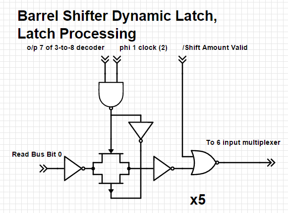
The data on the Read Bus is latched during phase 1 of the clock only when output 7 of the 3-to-8 decoder has been selected (i.e. all 3x inputs from the PLA are high). The latched data (or zero) is then available on one of the 6 inputs to the multiplexer. Zero is selected depending on the complex logic referred to earlier.
The output driver circuitry for each of the 7 signals is just two inverters in series.
The multiplexer circuitry, and decoding circuitry, is identical in form to the read bus input multiplexer I described in my earlier blog on register selection, and won't be repeated here.
Just the following "glue logic" circuits generate additional inputs to the multiplexer:

Note how the Shift Type in I-Reg b6 and I-Reg b5 are potentially adjusted, dependent on complex logic, in a similar manner to how the shift-amount described earlier might be adjusted.
The table below summarises the multiplexer's operation, and lists what the 7x outputs to the Barrel Shift Driver Logic are for each of the 8 combinations on the 3 signals from the PLA.

If we compare these PLA values, and the barrel-shifter outputs, with the values in the PLA output table from my previous article, it starts to makes sense.
Let's take row 1 of the PLA table as the first example. This row decodes a Data Processing instruction where Operand 2 is a register and the shift amount is immediate (i.e. the amount is in the instruction). The PLA values fed into the table above are "001" (row 1). This selects that the Shift Amount and Shift Type sent to the Barrel Shifter Driver Logic is b11..b5 of the DP instruction, exactly as we would expect.
Now let's examine an instruction that has the shift amount in a register - the situation I began this blog with. We see from the PLA table that this instruction type takes two cycles to execute (rows 2 and 3). The PLA values fed into the table above on the first cycle are "111" (row 7), which is a command to latch the content of the register which is present on the read bus. The PLA values on the second cycle are "000" (row 0), which feed the (possibly modified) values of the latch (for the shift amount) and the instruction's Shift Type to the Barrel Shifter Driver Logic.
We can now deal with the remaining PLA input types:
- "010" - this appears in a number of lines in the PLA output table where the result of the ALU is not used, and ensures the Carry bit, etc. are not inadvertently affected. It can be regarded as a no-op.
- "011" - appears only on row 27 of the PLA output table, and corresponds to the first instruction cycle of a Branch or Branch and Link instruction. In these cases the immediate value in the instruction is a word address, and the Barrel Shifter is instructed to shift this value left by two to convert it to a correct memory address.
- "100" - appears only on row 4 of the PLA output table, and corresponds to a DP instruction where operand 2 is immediate. In this case the value to be rotated is in the lowest 8 bits of the instruction, and is to be rotated right by twice the amount in b8..11 of the instruction (see the instruction format at the beginning of the blog). The "glue" logic chooses a Shift Type of "11" (Rotate Right) when the shift amount is non-zero or "00" (LSL) for when a 0 shift is selected.
- "101" - appears on row 7 and row 12 of the PLA output table. These both correspond to the last cycle of a LDR (Load Register from memory) instruction. Here, the Shift Amount is x8 the value appearing on Address line a0, a1. These address lines are only non-zero if a byte access has occurred, so this means that the lowest 8 bytes of data that has just been read from memory is rotated into it's correct position before being output from the barrel-shifter.
- Cycle 0 (row 15): selects "111" to save a register value in the barrel-shifter latch.
- Cycle 1 (row 16): selects "000", which shifts the number now on the read bus by the amount in the latch
- Cycle 2 (row 17): selects "001", perform a further shift, by the amount, and type specified in the instruction.
- Cycle 3 (row 18): selects "101", which corresponds the byte rotate operation associated with a LDR instruction.
From this set of steps we can make a guarded guess that this instruction is loading data from memory, and that, since it takes one more cycle than a standard LDR instruction, the address is calculated using the content of one register as a shift amount, in addition to the typical LDR address calculation. Our being able to accurately predict what the reserved instructions do will be a good test of the accuracy of the reverse-engineering!
Conclusion
We've now reverse-engineered the main logic associated with controlling the barrel-shifter. There remains some logic still to reverse-engineer for us to fully understand all the edge cases, but fortunately this logic is very isolated and does not detract from our wider understanding of how the barrel-shifter works and is controlled. We have also found that the barrel-shifter is put to extensive use for a variety of tasks, not just for the Data Processing (DP) instructions. We also have garnered some "teaser" information about one of the reserved instructions.
What is the software that was used to create the logic circuits of this power supply. Is it creately ?
ReplyDeleteI got my already programmed and blanked ATM card to withdraw the maximum of $1,000 daily for a maximum of 20 days. I am so happy about this because i got mine last week and I have used it to get $20,000. Mike Fisher Hackers is giving out the card just to help the poor and needy though it is illegal but it is something nice and he is not like other scam pretending to have the blank ATM cards. And no one gets caught when using the card. get yours from Mike Fisher Hackers today! *email cyberhackingcompany@gmail.com
DeleteSSN FULLZ AVAILABLE
DeleteFresh & valid spammed USA SSN+Dob Leads with DL available in bulk.
>>1$ each SSN+DOB
>>3$ each with SSN+DOB+DL
>>5$ each for premium fullz (700+ credit score with replacement guarantee)
Prices are negotiable in bulk order
Serious buyer contact me no time wasters please
Bulk order will be preferable
CONTACT
Telegram > @leadsupplier
ICQ > 752822040
Email > leads.sellers1212@gmail.com
OTHER STUFF YOU CAN GET
SSN+DOB Fullz
CC's with CVV's (vbv & non-vbv)
USA Photo ID'S (Front & back)
All type of tutorials available
(Carding, spamming, hacking, scam page, Cash outs, dumps cash outs)
SMTP Linux Root
DUMPS with pins track 1 and 2
WU & Bank transfers
Socks, rdp's, vpn
Php mailer
Sql injector
Bitcoin cracker
Server I.P's
HQ Emails with passwords
All types of tools & tutorials.. & much more
Looking for long term business
For trust full vendor, feel free to contact
CONTACT
Telegram > @leadsupplier
ICQ > 752822040
Email > leads.sellers1212@gmail.com
schematics.com
ReplyDeleteACTIVE & FRESH CC FULLZ WITH BALANCE
ReplyDeletePrice $5 per each CC
DETAILS
=>CARD TYPE
=>FIRST NAME & LAST NAME
=>CC NUMBER
=>EXPIRY DATE
=>CVV
=>FULL ADDRESS (ZIP CODE, CITY/TOWN, STATE)
=>PHONE NUMBER,DOB,SSN
=>MOTHER'S MAIDEN NAME
=>VERIFIED BY VISA
=>CVV2
*Time wasters or cheap questioners please stay away
*You can buy for your specific states too
*Payment in advance
Contact Us:
-->Whatsapp > +923172721122
-->Email > leads.sellers1212@gmail.com
-->Telegram > @leadsupplier
-->ICQ > 752822040
US FRESH, TESTED & VERIFIED SSN LEADS
$1 PER EACH
(INFO)
First Name | Last Name | SSN | Dob | Address | State | City | Zip | Phone Number | Account Number | Bank NAME | DL Number |
Home Owner | IP Address | MMN | Income
*Hope for the long term deal
*If anyone need leads In bulk, I'll definetly negotiate
US DUMP TRACK 1 & 2 WTIH PIN CODES ALSO AVAILABLE
Selling USA FRESH SSN Leads/Fullz, along with Driving License/ID Number with good connectivity.
ReplyDelete**PRICE FOR ONE LEAD/FULLZ 2$**
All SSN's are Tested & Verified. Fresh spammed data.
**DETAILS IN LEADS/FULLZ**
->FULL NAME
->SSN
->DATE OF BIRTH
->DRIVING LICENSE NUMBER
->ADDRESS WITH ZIP
->PHONE NUMBER, EMAIL
->EMPLOYEE DETAILS
->Bulk order negotiable
->Minimum buy 25 to 30 leads/fullz
->Hope for the long term business
->You can asked for specific states too
**Contact 24/7**
Whatsapp > +923172721122
Email > leads.sellers1212@gmail.com
Telegram > @leadsupplier
ICQ > 752822040
I was searching for a loan to sort out my bills & debts, then I saw comments about Blank ATM Credit Cards that can be hacked to withdraw money from any ATM machines around you . I doubted this but decided to give it a try by contacting { officialblankatmservice@gmail.com} they responded with their guidelines on how the card works. I was assured that the card can withdraw $5,000 instant per day & was credited with $50,000,000.00 so i requested for one & paid the delivery fee to obtain the card, after 24 hours later, i was shock to see the UPS agent in my resident with a parcel {card} i signed and went back inside to pick up my car key and drove to a nearest ATM machine to confirmed if the card really work to my greatest surprise it did.. This is no doubt because I have the card & have made use of the card. These hackers are UK based hackers set out to help people with financial freedom!! Contact them via email: officialblankatmservice@gmail.com or WhatsApp +447937001817 if you want to get rich.
ReplyDeleteAll thanks to Mr Anderson for helping with my profits and making my fifth withdrawal possible. I'm here to share an amazing life changing opportunity with you. its called Bitcoin / Forex trading options. it is a highly lucrative business which can earn you as much as $2,570 in a week from an initial investment of just $200. I am living proof of this great business opportunity. If anyone is interested in trading on bitcoin or any cryptocurrency and want a successful trade without losing notify Mr Anderson now.Whatsapp: (+447883246472 )
ReplyDeleteEmail: tdameritrade077@gmail.com